| Product | Description | Data Sheet |
|---|---|---|
| 904 | Accepts battery voltage between 1.8 – 6.5V. Optimized for operation with 1-4 LEDs at 1A. Capable of driving external FETs if more power is desired. |  |
| 905 | Accepts battery voltage between 1.8 – 6.5V. Can accommodate up to 10 LEDs at 1A. Capable of driving external FETs if more power is desired. | |
| 906 | Accepts battery voltage between 3.8 – 35V. Can accommodate up to 10 white LEDs at 1A. Capable of driving external FETs if more power is desired. | |
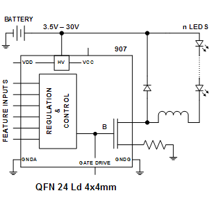
| 907 | Accepts battery voltage between 3.8 – 40V. Buck converter. Can accommodate LEDs up to 1.5A. Capable of driving external FET if more power is desired. | |
| Document | Description | Data Sheet |
|---|---|---|
| AN400010 | This application note provides examples and explains how to get the most from the 904, 905, 906 and 907 parts. (2.5 MB) | |
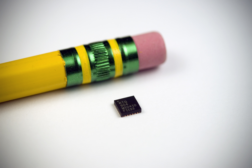
Each product in the 904 – 907 family has been designed for a particular range of battery and LED combination. Off-current is typically 5 uA, and allows continuous connection to the battery.
The 904 and 905 have been designed for 1.8 to 6.5 volt battery applications. The 904 has the lowest on resistance and can support up to 20 volt LED loads. Although the 905 has higher on resistance, it can support up to 40 volt LED loads.
The 906 and 907 have been designed for 5 to 40 volt battery applications. An internal series regulator generates the low voltage for logic and gate drive. The 906 is designed for either a boost or SEPIC topology. The 907 uses the buck topology to step down the battery voltage to the lower LED voltage.
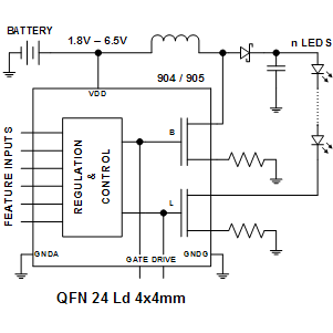
These products can drive LEDs from 2 to 40 volts at up to 1 Ampere without external power FETs. If additional power handling is required, gate driver outputs are provided to drive external power FETs in paralleled with the internal power devices.
The LED current is set by one external resistor. Constant-current, pulse width modulation (PWM) is used to control the LED brightness over a 128 to 1 range.
The 904 – 906 products use either a boost or SEPIC architecture to generate the correct LED voltage. The current through the LED is used to regulate the boost / SEPIC section. The maximum current through boost / SEPIC section is 2.6 A peak without an external power FET. The maximum LED current is 1 Ampere without an external power FET.
The 907 product uses the buck topology to directly generate the LED current. The peak inductor current is set to twice the desired LED current. The 907 can drive LEDs up to 1.5 A (3 A peak) without an external power FET. In a 36 V application, the 907 can deliver 30 watts to a 21 V LED module and regulate the brightness over a 128 to 1 range.
The 904 – 907 products have 15 brightness settings with logarithmic steps to cover the 128 to 1 brightness range. Constant-current pulse width modulation at 244 Hz provides consistent light quality and fine resolution from low to high illumination levels without flicker or undesirable artifacts. At low illumination levels, fine resolution is critical for nighttime tasks where too much light will impair the users night vision and jeopardize the mission.
Below is a representative palette of the 15 illumination settings. Each of these brightness setting can be used with the special modes of flashing and SOS.

The default brightness is 4 steps below full brightness. This give 4 times the battery life as compared to full brightness. The user can increase the brightness with the U input, or decrease the brightness with the D input. These inputs operate similarly to the volume control on a sound system. If held “ON” they will auto-increment or auto-decrement the brightness. The ability to finely adjust the light output allows the user to maximize battery life while providing just the right amount of illumination.
In addition, there is a full brightness input (FB) to immediately switch from any brightness setting to full brightness and then back to the prior setting without cycling through the other brightness settings. This input can be used for signaling or quick inspection of distant objects without the necessity of cycling through other brightness settings.
The products were designed to be continuously connected to the battery with negligible impact on battery life. Switching the product off through the EN or MO inputs does not disturb the brightness or mode setting. The user can immediately switch from the off state to their last desired state without cycling through unwanted brightness or modes settings. This feature eliminates the need for mechanical latching switches or microcontrollers to adjust the brightness or control the modes.
Active power management maintains constant current to the LED as the battery voltage decreases. This is called a constant power load, rather than a constant resistance or constant current load. The brightness of the LED does not change as the battery discharges. The light output may suddenly collapse when the battery runs out of charge.
To prevent the user from being left in the dark without warning, a low battery detection circuit flickers the light output every 16 seconds when the battery is near the end of its life. The warning period can be used to reduce the brightness and extend the remaining battery charge. The voltage threshold for this warning is set by two external resistors.
Rechargeable batteries are most sensitive to over-discharge. To prevent over-discharge, a second threshold that is 7 percent lower than the warning threshold is used to shut-off the device. The product can be turn-on again but will warn and shut-off again.
Many batteries have been accidentally depleted by leaving the light on when its not needed. Built into the 904 through 907 products is a user-enabled, automatic shut-off mode. The automatic shut-off feature disables the product after 18 minutes. Prior to shut-off, the light will modulate for 2 minutes to warn the user of automatic shut-off. During automatic shut-off warning, activating either D or U inputs will reset the timer for an additional 18 minutes without changing the brightness.
Automatic shut-off mode is enabled by increasing to full brightness with the U input, releasing U, and then re-engaging U for at least one second. The LED will briefly flash off 4 times to indicate that automatic shut-off has been enabled.
To disable automatic shut-off, the product is set to minimum brightness by the D input, releasing D, and then re-engaging D for at least 2 seconds. The light will very briefly flash at full brightness a few times to indicate the automatic shut-off has been disabled.
Special modes can be accessed from any brightness setting by simultaneously activating both D and U brightness inputs for more than 2 seconds. While in any of the special modes, the brightness can be continuously adjusted with either D or U.
The flashing beacon is the first mode entered, and uses doublet flashes repeating 65 times per minute. The automatic shut-off feature is disabled while in the flashing beacon mode. When the battery is low, the pattern changes to an alternating pattern of single and double flashes to indicate a low battery condition.
To exit the flashing beacon mode, both D and U inputs are simultaneously activated for more than 1 seconds. After 1 second the product will return to normal mode.
In the SOS mode the product will modulate the LED to produce the Morse Code for SOS. To enter the SOS mode the product must first enter the flashing mode and then while exiting the flashing mode both D and U inputs are held activate for more than 4 seconds.
The automatic shut-off and low battery warning features are inactive while in the SOS mode. To exit the SOS mode, both D and U inputs are simultaneously activated for more than 1 second.
Switching the product off through the EN or MO inputs does not disturb the brightness or mode setting. If both D and U input are permanently set active, the product will always be in the flashing beacon mode. In that configuration, only the FB input controls the brightness.
Portable LED lighting products use a diverse combination of LEDs and batteries. The 904 – 907 products match the batteries to the LEDs while giving the consumer unprecedented control over the brightness and functionality of the lighting product. An application document explains how to get the most from the 904, 905, 906 and 907 parts and provides design examples using boost, SEPIC, or buck topologies. Application boards are available to demonstrate each of these topologies and the product features:
| V LED | I LED (mA) | Typical LED | Pwr (W) | Battery (VBAT) | Topology | Part | Ext. FET | App. Board | Ver |
|---|---|---|---|---|---|---|---|---|---|
| 3.2 | 360 | 1-XPG | 1.2 | 1.8 to 3.2 | Boost | 904 | 50804 | 01 | |
| 1.8 to 6.5 | SEPIC | 904 | 50808 | 01 | |||||
| 3.3 | 720 | 1-XPG | 2.4 | 5.4 to 15 | Buck | 907 | 50807 | 01 | |
| 6.4 | 1000 | 2-XPG | 6.4 | 5.4 to 15 | SEPIC | 906 | * | 50806 | 01 |
| 10.7 | 120 | MX3S | 1.3 | 1.8 to 6.5 | Boost | 904 | 50804 | 02 | |
| 12.8 | 360 | 4-XPG | 4.6 | 2.7 to 6.5 | Boost | 904 | 50804 | 03 | |
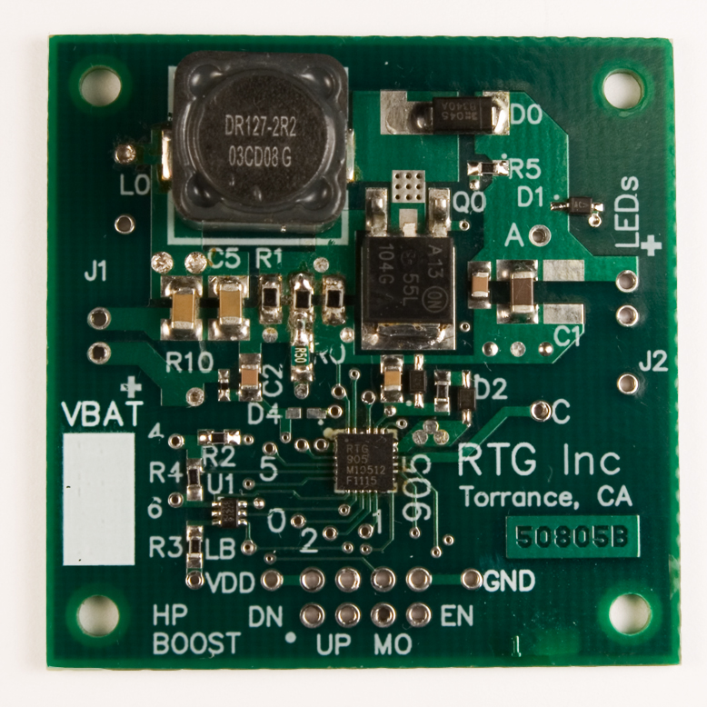
| 31.5 | 360 | 9-XPG | 11.3 | 3.6 to 6.5 | Boost | 905 | * | 50805 | 01 |
| 1000 | 31.5 | 10.8 to 15 | Boost | 906 | * | 50805 | 02 |
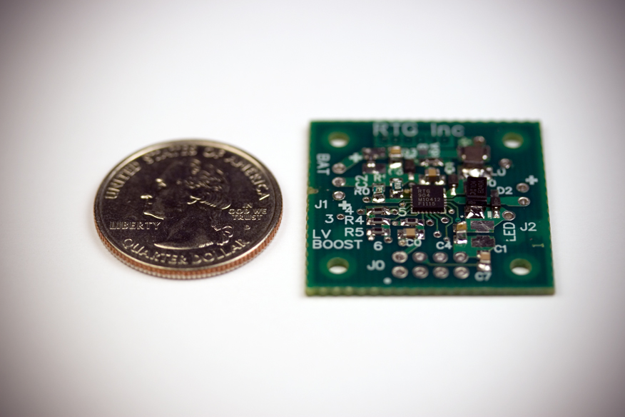
These boards have been designed to allow the electronic designer to modify and try different component values. Silk screen markings and ample component spacing make them easily modified with surface mount rework stations.
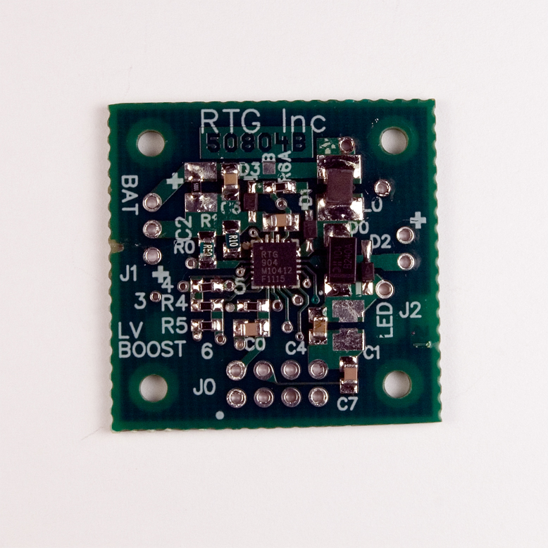
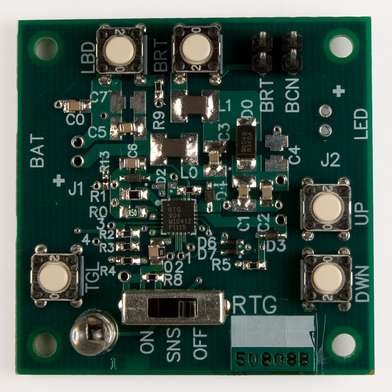
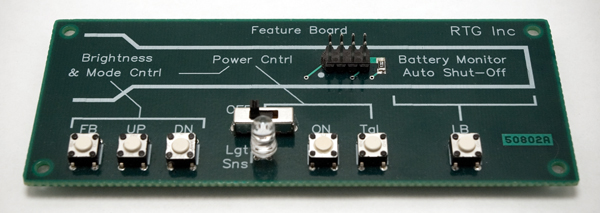
The 50808 board has feature switches included, whereas the other boards have solder terminals for interconnection between the board and external switches, which facilitates temperature testing.
For the convenience of the evalulation engineer, the 50802 “Feature Board” with switches, light sensor, descriptive graphics, and connectors is available to control and demonstrate the 50804 – 50807 boards.